
Volume Boot Record (VBR): Structure, Location, and Boot Process
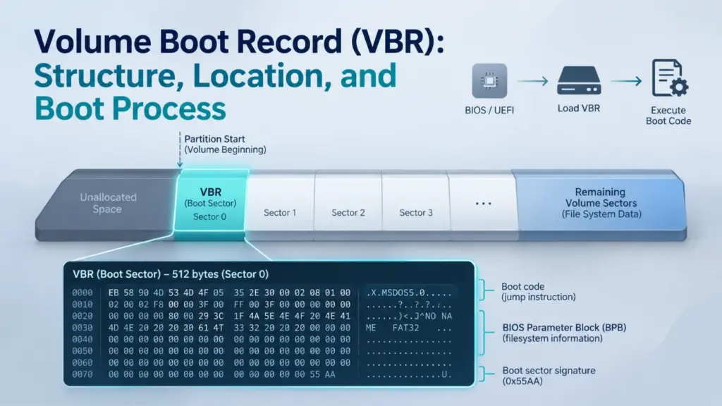
A Volume Boot Record (VBR) is a boot-related data structure stored at the beginning of a file system volume. It contains information that describes the volume’s layout and may also include bootstrap code used during legacy startup. Although the VBR is commonly associated with the first sector of a partition, its exact structure and role depend on the file system and boot architecture.
This distinction matters because a VBR is not the same as an MBR, and modern UEFI-based Windows systems do not normally execute traditional VBR bootstrap code during startup.
목차
What Is a Volume Boot Record?
A Volume Boot Record is the initial boot-related structure of a volume. It is also commonly called a volume boot sector or, in many PC storage contexts, a partition boot record (PBR).
The VBR serves two related purposes:
- Volume identification and description: It stores parameters that help software interpret the file system, such as sector size, cluster size, volume length, and file-system-specific metadata locations.
- Bootstrap support: Depending on the file system and boot environment, it may contain executable code that transfers control to the next stage of an operating system’s boot process.
The exact contents are not universal. A FAT32 boot sector, an NTFS boot sector, and an exFAT Main Boot Sector all describe their respective volumes differently.
For example, a FAT32 boot sector contains a BIOS Parameter Block (BPB), while an exFAT Boot Sector uses fields such as VolumeLength, FatOffset, 및 ClusterHeapOffset. These structures serve related purposes, but they are not interchangeable.
VBR, Volume Boot Sector, and Partition Boot Record
The terms Volume Boot Record, Volume Boot Sector, 및 Partition Boot Record are frequently used interchangeably, although terminology varies between technical sources.
A useful distinction is:
- Volume Boot Sector: Usually refers to the first sector of a file system volume.
- Volume Boot Record: Often refers to the boot-related structure stored at the beginning of that volume. Some file systems define a larger boot region rather than a single-sector structure.
- Partition Boot Record: Usually refers to the boot sector at the beginning of a partition.
On a conventional basic disk where a partition directly contains a volume beginning at the same address, the PBR and VBR generally refer to the same sector.
However, the terms describe different storage concepts. A partition defines a region of a disk, while a volume represents the storage space organized for a file system. They should not be assumed to have a one-to-one relationship in every storage configuration.
Where Is the Volume Boot Record Located?
그리고 VBR is located at the beginning of its file system volume.
On a conventional partitioned disk, the volume begins at the partition’s starting logical block address (LBA). Therefore, the VBR is normally found at the first logical sector of that partition.
Consider an illustrative disk layout:
Disk region | Starting LBA | 목적 |
MBR or Protective MBR | 0 | Disk-level compatibility and partition information |
기본 GPT 헤더 | 1 (GPT disk) | Describes the GPT layout |
Partition 1 | 2,048 | First partition begins |
Partition 1 VBR | 2,048 | First volume’s boot sector |
Partition 2 | Another partition start | Second partition begins |
Partition 2 VBR | Partition 2 start | Second volume’s boot sector |
The example assumes that each partition directly contains a volume and uses a logical sector size of 512 bytes. The actual starting LBA depends on the disk layout.
For a partition beginning at LBA 2,048, the VBR is at LBA 2,048 relative to the physical disk, not at LBA 0.
An unpartitioned device can also contain a file system volume. In that case, the volume may begin at the device’s first logical sector, so a separate MBR or GPT partition table is not necessarily present.
Why the VBR Is Not Always at Disk LBA 0
The first logical sector of a disk and the first logical sector of a volume are different address locations.
- Disk LBA 0 identifies the beginning of the disk.
- Volume-relative sector 0 identifies the beginning of the volume.
- The partition’s starting LBA connects these two address spaces on a conventional partitioned disk.
Confusing these locations can cause a disk editor or diagnostic tool to inspect the wrong sector.
For a deeper explanation of the disk-level structure, see the MBR 파티션 테이블.
VBR vs. MBR: What Is the Difference?
The main difference between a VBR and MBR is their storage level and responsibility.
An MBR belongs to the disk-level partitioning structure. A VBR belongs to a file system volume.
기능 | MBR | VBR |
Storage level | Disk level | Volume level |
일반적인 위치 | Disk LBA 0 | First sector of the volume |
Main contents | Bootstrap code, partition entries, disk signature | File-system parameters and, depending on the format, bootstrap code |
주요 목적 | Describe the legacy disk partition layout and provide a boot entry point | Describe the volume and support applicable boot processes |
File-system dependency | Does not define the complete layout of an individual file system | Its structure depends on the file system |
Backup arrangement | No standard backup MBR | Depends on the file system |
On a conventional MBR-partitioned disk, the MBR contains four partition entries, each describing a partition’s location and size. Its bootstrap code can locate the selected boot partition and transfer control to that partition’s boot sector.
The VBR then provides volume-specific information and, in a traditional BIOS boot chain, may execute the next bootstrap stage.
그리고 Amagicsoft MBR 파티션 테이블 안내서 explains the disk-level partition entries in more detail.
How Does VBR Relate to GPT?
GPT and VBR describe different parts of the storage architecture.
GPT defines the disk’s partition layout. It contains a primary GPT Header, a partition entry array, and corresponding backup structures. A GPT disk also normally contains a Protective MBR at LBA 0.
A VBR, by contrast, belongs to the file system volume inside a partition.
A simplified GPT disk layout is:
- Protective MBR at LBA 0.
- Primary GPT Header at LBA 1.
- Primary GPT Partition Entry Array.
- Usable disk space containing partitions.
- Backup GPT structures near the end of the disk.
The file system volume begins at the start of its partition, where its boot sector or boot region is located.
Therefore, a GPT disk can contain NTFS, FAT32, and exFAT volumes with their own volume boot structures.
GPT does not replace the VBR. It defines where partitions begin and end, while the file system defines how data inside a volume is organized.
다음 내용을 참조하십시오. Amagicsoft GPT guide for a deeper explanation of GPT headers and partition entries.
How the VBR Fits into the Windows Boot Process
INTERACTIVE BOOT-PATH EXPLORER
Choose a firmware mode to see how Windows reaches its boot manager—and whether traditional VBR bootstrap code is part of that path.
-
1Firmware BIOS Initializes the platform and selects a boot device.
-
2Disk-level boot record · LBA 0 MBR bootstrap code Uses the legacy partition information to locate the selected boot partition.
-
3Volume-level boot record · Partition start VBR / PBR bootstrap code Receives control in the conventional BIOS/MBR chain and starts the next boot stage. TRADITIONAL VBR CODE EXECUTES
-
4Windows 부팅 관리자
bootmgrReads the boot configuration and selects the Windows loader. -
5Operating-system loader
winload.exeLoads the Windows kernel and required boot-start drivers.
-
1Firmware UEFI Boot Manager Uses firmware boot options to identify a device and an EFI application.
-
2Disk partition layout GPT and the EFI System Partition The firmware identifies the system partition. A Windows UEFI system disk uses GPT; its ESP is FAT32.
-
3EFI application on the ESP
\EFI\Microsoft\Boot\bootmgfw.efiUEFI loads this file through filesystem services. It does not execute the traditional x86 bootstrap code in the MBR or VBR. EFI FILE IS LOADED -
4Windows OS Loader
winload.efiLoads the Windows kernel and required boot-start drivers.
In a conventional Legacy BIOS/MBR Windows boot, the partition boot record is an executable stage in the chain. Its location is volume-level, not disk LBA 0.
The ESP still has a FAT32 filesystem boot sector because it is a formatted volume. However, the normal UEFI Windows path loads an EFI application as a file; it does not run the legacy VBR bootstrap code.
Educational model of a typical Windows boot path. Actual boot configurations can include recovery entries, additional boot managers, or vendor-specific stages. This module does not inspect a physical disk.
The role of the VBR depends on whether Windows starts through Legacy BIOS or native UEFI.
These environments use different mechanisms to locate and load the Windows boot manager.
Legacy BIOS and MBR Boot Sequence
On a conventional Legacy BIOS system using an MBR-partitioned system disk, the boot process follows this general sequence:
- BIOS initializes the computer and selects a boot device.
- BIOS loads the MBR from disk LBA 0.
- The MBR bootstrap code locates the selected boot partition.
- The partition’s first sector, commonly called the VBR or PBR, receives control.
- The VBR bootstrap code starts the next boot stage, which leads to Windows Boot Manager (
bootmgr). - Windows Boot Manager loads
winload.exe. - The Windows loader initializes the kernel and required boot-start drivers.
In this configuration, the VBR is an executable stage in the traditional boot chain.
The partition boot sector is not responsible for defining the entire disk layout. It operates after the disk-level boot code has identified the boot partition.
UEFI Boot Sequence and the EFI System Partition
A native UEFI Windows installation uses a different boot process.
Instead of executing traditional MBR and VBR bootstrap code, UEFI firmware uses its Boot Manager to locate and load an EFI application.
A typical Windows UEFI boot sequence is:
- UEFI firmware initializes the platform.
- The firmware reads its boot options and identifies the EFI System Partition (ESP).
- The firmware accesses the ESP’s file system and loads
\EFI\Microsoft\Boot\bootmgfw.efi. - Windows Boot Manager loads
winload.efi. - The Windows loader initializes the kernel and required boot-start drivers.
그리고 Microsoft Windows startup troubleshooting documentation distinguishes the BIOS and UEFI startup phases and identifies the different Windows Boot Manager and OS Loader paths.
The UEFI specification also explains that its Boot Manager loads UEFI applications from files rather than executing traditional legacy MBR bootstrap code. See the UEFI Specification: Overview 그리고 GPT Disk Layout.
Does UEFI Still Have a VBR?
Yes. A UEFI system can still contain volume boot sectors.
For a standard Windows UEFI/GPT installation, the EFI System Partition is formatted with FAT32. Consequently, it has a FAT32 file system boot sector and the associated file-system structures.
However, the normal UEFI boot process does not execute the traditional x86 bootstrap code stored in that VBR. Instead, the firmware accesses the FAT32 file system and loads the EFI boot manager as a file.
This distinction is important:
- The ESP’s VBR exists as part of the FAT32 volume structure.
- The EFI application is the executable entry point used by native UEFI startup.
- The presence of a VBR does not mean that its traditional bootstrap code must execute.
마이크로소프트의 UEFI/GPT-based hard drive partition guidance specifies the FAT32 requirement for the Windows EFI System Partition.
Volume Boot Sector Structure: What Does a VBR Contain?
There is no single universal volume boot sector structure shared by every file system.
A typical boot sector may contain several types of information:
구성 요소 | 목적 |
Jump instruction | Transfers execution to bootstrap code when applicable |
File-system identifier | Identifies or describes the file system format |
BIOS Parameter Block (BPB) or equivalent fields | Describes sector size, cluster size, volume size, and other parameters |
File-system-specific fields | Identifies important structures or their locations |
Bootstrap code | Provides instructions for a compatible boot environment |
Signature or checksum information | Helps identify or validate specific parts of the structure |
The exact fields, byte offsets, lengths, and validation rules depend on the file system.
For example, the FAT specification defines a BPB, while exFAT defines its own Main Boot Sector fields. Treating these formats as identical can lead to incorrect interpretation of raw disk data.
The BIOS Parameter Block (BPB)
The BIOS Parameter Block is a collection of fields describing fundamental file-system parameters.
In FAT file systems, the BPB is located in the first sector of the volume. It provides information such as:
- Bytes per sector.
- Sectors per cluster.
- Number of reserved sectors.
- Number and size of FAT structures.
- Total volume sectors.
- Root directory information, where applicable.
FAT32 extends the BPB with additional fields for its root directory cluster, FSInfo sector, and backup boot sector.
The BPB is not the entire VBR. It is one part of the boot sector’s structure.
그리고 Microsoft FAT Specification provides the field definitions and byte offsets for FAT12, FAT16, and FAT32.
Why the 55 AA Signature Does Not Prove a VBR Is Valid
Many traditional boot-sector formats use the two bytes 55 AA at offsets 510–511 as a boot signature.
This marker is useful when inspecting a sector, but it is not sufficient to establish that the complete structure is valid.
A sector may contain the expected signature while still having:
- Incorrect sector or cluster parameters.
- Invalid volume-length information.
- File-system-specific fields outside their allowed ranges.
- Inconsistent references to other file-system structures.
- Damaged or incomplete bootstrap code.
A valid signature only confirms the presence of that particular marker. It does not prove that the volume can be mounted, that all metadata is intact, or that the boot process can complete.
Some file systems also define additional validation mechanisms. For example, exFAT uses a Boot Checksum for its Main and Backup Boot Regions.
How VBR Structures Differ Across NTFS, FAT32, and exFAT
Although NTFS, FAT32, and exFAT all have boot-related structures at the beginning of a volume, their layouts and backup mechanisms differ significantly.
NTFS Boot Sector
An NTFS volume begins with an NTFS boot sector containing file-system parameters and bootstrap-related fields.
The common 512-byte NTFS boot-sector layout documented in the Linux-NTFS on-disk structure definition includes:
Byte offset | 필드 | 크기 | 목적 |
| Jump instruction | 3바이트 | Bootstrap entry instruction |
| OEM ID | 8바이트 | Identifies NTFS using |
| BPB | 25 bytes | Basic volume parameters |
| Number of sectors | 8바이트 | Volume sector count |
|
| 8바이트 | Starting logical cluster number of the Master File Table |
|
| 8바이트 | Starting logical cluster number of the MFT mirror |
| Clusters per MFT record | 1바이트 | Defines the MFT record-size encoding |
| Clusters per index record | 1바이트 | Defines the index-record-size encoding |
| Volume serial number | 8바이트 | Identifies the volume |
| Checksum field | 4바이트 | Boot-sector checksum field |
| Bootstrap area | 426 bytes | Boot-related code and reserved space |
| End-of-sector marker | 2바이트 |
|
Boot sector & end-of-partition spare
ILLUSTRATIVE · NTFS1 GiB sample · 512 B/sector · 4 KiB/cluster · partition starts at disk LBA 2,048
Decoded field
Layout, sample notes & source
NTFS. The conventional NTFS total-sectors field here is 2,097,151, excluding the final spare sector; the containing partition has one additional sector. The spare is therefore at volume sector 2,097,151, not field value minus one. $Boot is illustrated as a 16-sector initial area; only its first sector is duplicated at the partition end. $MFTMirr is a separate metadata mirror. The signed record-size byte F6 means −10 → 2¹⁰ = 1,024 bytes. Unused bytes and the unused legacy checksum are zero; bootstrap filler is F4.
Constructed teaching bytes, not a disk capture or mountable image. Offsets are sector-local hex; integer fields use little-endian encoding. Disk LBA = 2,048 + volume sector. All sector ranges are inclusive; the map is schematic. Select a field or click its bytes; dots in ASCII mark nonprintable bytes. Bootstrap content is teaching filler.
This table describes the layout documented by the Linux-NTFS implementation. It is a useful on-disk structure reference, not a substitute for a complete Microsoft NTFS specification.
One particularly important field is $MFT LCN.
LCN means Logical Cluster Number. It identifies a cluster relative to the NTFS volume, not a physical disk LBA.
만약 $MFT LCN is known, the starting location of the Master File Table can be calculated using the volume’s cluster size:
MFT byte offset = MFT LCN × bytes per cluster
This does not identify every file’s location. It identifies the starting location of the $MFT 구조입니다.
그리고 $MFTMirr field identifies the location of a limited mirror of important initial MFT records. It is not a complete backup of the Master File Table or user files.
For a deeper explanation of this relationship, see the Amagicsoft Master File Table guide.
The Linux-NTFS on-disk layout also documents a backup boot sector at the final sector of the partition for Windows NT 4.0 and later, while older NT 3.51 and earlier systems used a different location. This is an implementation and historical reference; the actual volume layout should be checked before assuming a backup location.
FAT32 Boot Sector, FSInfo, and Backup Boot Record
FAT32 uses a BPB in the first sector of the volume’s Reserved Region.
Several fields are particularly important:
필드 | Byte offset | 크기 | 목적 |
| 11 | 2바이트 | Bytes per sector |
| 13 | 1바이트 | Sectors per cluster |
| 14 | 2바이트 | Reserved-region size |
| 36 | 4바이트 | Sectors occupied by one FAT |
| 44 | 4바이트 | First cluster of the root directory |
| 48 | 2바이트 | Location of the FSInfo sector |
| 50 | 2바이트 | Location of the backup boot record |
BPB, FSInfo & backup boot record
ILLUSTRATIVE · FAT321 GiB sample · 512 B/sector · 4 KiB/cluster · partition starts at disk LBA 2,048
Decoded field
Layout, sample notes & source
FAT32. This sample uses a Microsoft-style three-sector boot record at 0–2, copied to 6–8, inside 32 reserved sectors. Sector 1 is FSInfo and sector 7 its initial copy; the authoritative FSInfo address remains 1. Boot-code sectors use F4 filler. The remaining reserved sectors are zero. With two 2,048-sector FATs, data begins at 4,128; floor((2,097,152 − 4,128) / 8) = 261,628 clusters, above the FAT32 threshold of 65,525. Each FAT holds 262,144 entries, sufficient for 261,630 required entries. FSInfo allocation hints are explicitly unknown.
Constructed teaching bytes, not a disk capture or mountable image. Offsets are sector-local hex; integer fields use little-endian encoding. Disk LBA = 2,048 + volume sector. All sector ranges are inclusive; the map is schematic. Select a field or click its bytes; dots in ASCII mark nonprintable bytes. Bootstrap content is teaching filler.
그리고 BPB_FSInfo field normally points to sector 1. This sector stores information such as the last known free-cluster count and the next free-cluster hint.
그리고 BPB_BkBootSec field identifies the backup boot record location. In the Microsoft FAT specification, its value is 0 or 6. When set to 6, the backup structure starts at volume-relative sector 6.
An important detail is that the FAT32 boot record is not simply a single-sector copy. The Microsoft specification describes the complete boot record as three sectors long, with a corresponding backup sequence. A copy of the FSInfo structure is also maintained in the backup sequence.
These structures serve different purposes:
- The boot sector contains the BPB and boot-related information.
- FSInfo stores free-space hints.
- The backup boot record provides an alternative copy of important boot information.
FSInfo is not a second VBR, and its free-cluster count is not necessarily an exact, continuously updated value.
exFAT Main and Backup Boot RegionsexFAT uses a more extensive structure called the Boot Region.
에 따르면 Microsoft exFAT File System Specification, the volume contains a Main Boot Region and a Backup Boot Region, each occupying 12 sectors.
Volume-relative sector | Main Boot Region | Backup Boot Region |
0 / 12 | 부팅 섹터 | Backup Boot Sector |
1–8 / 13–20 | Extended Boot Sectors | Backup Extended Boot Sectors |
9 / 21 | OEM Parameters | Backup OEM Parameters |
10 / 22 | 예약됨 | Backup Reserved |
11 / 23 | Boot Checksum | Backup Boot Checksum |
The Main Boot Sector contains the primary parameters used to describe the exFAT volume.
Important fields include:
필드 | Byte offset | 크기 | 목적 |
| 0 | 3바이트 | Bootstrap jump instruction |
| 3 | 8바이트 | Identifies the file system as exFAT |
| 64 | 8바이트 | Media-relative partition offset |
| 72 | 8바이트 | Volume length in sectors |
| 80 | 4바이트 | Starting sector of the first FAT |
| 84 | 4바이트 | Length of each FAT |
| 88 | 4바이트 | Starting sector of the Cluster Heap |
| 92 | 4바이트 | Number of clusters in the Cluster Heap |
| 96 | 4바이트 | Starting cluster of the root directory |
| 106 | 2바이트 | File-system status flags |
| 108 | 1바이트 | Sector-size encoding |
| 109 | 1바이트 | Cluster-size encoding |
| 110 | 1바이트 | Number of FAT structures |
| 112 | 1바이트 | Reported percentage of allocated clusters |
Main & backup boot regions
ILLUSTRATIVE · exFAT1 GiB sample · 512 B/sector · 4 KiB/cluster · partition starts at disk LBA 2,048
Decoded field
Layout, sample notes & source
exFAT. Sectors 0–11 and 12–23 form separate 12-sector boot regions. The checksum is computed from the preceding 11 sectors of each region, skipping boot-sector bytes 106, 107 and 112, then repeated 128 times in its checksum sector. Main and backup start identical in this sample; backup flags and percent-used are treated as stale by readers. No bootstrap is supplied: main boot-code bytes are F4; extended code is zero. OEM parameters are null; reserved bytes are zero. The heap has 261,632 clusters; root cluster 12 leaves room for bitmap and up-case metadata, whose contents are outside this lab.
Constructed teaching bytes, not a disk capture or mountable image. Offsets are sector-local hex; integer fields use little-endian encoding. Disk LBA = 2,048 + volume sector. All sector ranges are inclusive; the map is schematic. Select a field or click its bytes; dots in ASCII mark nonprintable bytes. Bootstrap content is teaching filler.
Unlike the traditional FAT BPB, exFAT defines its own parameter layout. Its MustBeZero field also occupies the range corresponding to the FAT12/16/32 BPB area, helping prevent older FAT implementations from mistakenly interpreting an exFAT volume as a FAT volume.
How the exFAT Boot Checksum Works
The exFAT Boot Checksum provides a stronger validation mechanism than checking a signature alone.
The specification defines the following process:
- Read the first 11 sectors of the Main Boot Region.
- Exclude the
VolumeFlagsbytes at offsets 106–107 and thePercentInUsebyte at offset 112. - Process the remaining bytes in order.
- For each byte, rotate the current 32-bit checksum right by one bit and add the byte value, keeping the result within 32 bits.
- Store the resulting checksum as a repeating four-byte pattern throughout the Boot Checksum sector.
The Backup Boot Region has its own corresponding checksum calculation.
The exclusion of VolumeFlags 그리고 PercentInUse is intentional. These fields can be updated without recalculating the Boot Checksum. The specification also states that the corresponding values in the Backup Boot Sector must be treated as stale.
This means that a byte-for-byte comparison of the Main and Backup Boot Regions is not an appropriate universal validation method.
Instead, each region must be checked according to its own checksum and field-validity rules.
How to Inspect and Validate a Volume Boot Record
Inspecting a VBR requires knowing where the volume begins and which file system defines its layout.
A raw sector should not be interpreted using a generic template without first identifying the volume format.
Step 1: Identify the Volume’s Starting LBA
Determine the partition or volume starting position using reliable disk-layout information.
On a conventional basic disk, the partition’s starting LBA is normally the starting position of its contained volume.
Do not assume that every volume begins at LBA 0 or that a drive letter identifies a physical disk offset.
Step 2: Calculate the Byte Offset
To locate the volume’s first sector in a raw disk image, use:
Byte offset = Volume starting LBA × Logical sector size
For example, if a partition begins at LBA 2,048 and the device uses 512-byte logical sectors:
2,048 × 512 = 1,048,576 bytes
The VBR begins at byte offset 1,048,576 in that illustrative disk image.
For a 4,096-byte logical sector, the same LBA would correspond to a different byte offset. Always use the device’s actual logical sector size rather than assuming every disk uses 512-byte sectors.
Step 3: Inspect the Structure Using a Hex Editor
A disk editor or hex editor can display the raw sector bytes and their offsets.
For a read-only inspection:
- Open a disk image or the correct physical device using a suitable hex editor.
- Navigate to the calculated byte offset.
- Examine the initial bytes and file-system identifier.
- Interpret the relevant fields using the corresponding file-system specification.
- Check whether the field values are internally consistent.
For example, an NTFS boot sector should be interpreted using its NTFS field layout, while a FAT32 sector should be interpreted using the FAT32 BPB definitions.
Do not edit the source disk while performing an inspection. When the source contains important data, a read-only image is preferable.
Step 4: Check File-System-Specific Consistency
A VBR should be evaluated using multiple indicators rather than a single signature.
Useful checks include:
- Whether the reported bytes-per-sector value is valid for the format.
- Whether sectors-per-cluster is an allowed value.
- Whether the volume length fits within the available partition or volume extent.
- Whether file-system-specific offsets point to plausible locations.
- Whether backup structures are located where the relevant format specifies.
- Whether required checksums and signatures validate.
For FAT32, inspect the BPB fields and the relationship between the boot sector, FSInfo, and backup boot record.
For NTFS, examine the volume-sector count and MFT-related cluster locations. A plausible $MFT LCN does not by itself prove that the MFT is intact.
For exFAT, validate the Main and Backup Boot Checksums independently and confirm that the relevant fields are within their specified ranges.
Step 5: Interpret the Results Carefully
A successful signature check does not prove that a volume is healthy.
Similarly, a valid backup boot structure does not prove that all file-system metadata or user data remains intact.
A proper assessment should distinguish between:
- A readable boot sector.
- Structurally valid file-system parameters.
- A valid backup structure.
- A mountable file system.
- An executable and complete operating-system boot chain.
These are related but different conditions.
What Happens When a Volume Boot Record Is Damaged?
Damage to a Volume Boot Record can prevent a system from starting or make a volume difficult to identify and mount.
The exact impact depends on which fields or structures are affected and how the operating system uses them.
피해 | Possible result |
Bootstrap code damage | Traditional BIOS startup may fail |
BPB or volume-parameter damage | The file system may not be recognized or mounted correctly |
Invalid NTFS boot information | NTFS volume interpretation may fail |
FAT32 boot-sector damage | FAT32 mounting or boot operations may be affected |
exFAT Boot Region inconsistency | File-system identification or validation may fail |
Main boot structure damage with a valid backup | Recovery may be possible using the appropriate file-system-specific procedure |
VBR Damage Does Not Automatically Mean File Deletion
A VBR contains structural and boot-related information. It does not normally store the contents of ordinary user files.
Therefore, damage to a VBR does not automatically mean that photos, documents, videos, or other file contents have been erased.
For example, an NTFS volume may have a damaged boot sector while some or all of its MFT records and user-data clusters remain readable.
However, recovery depends on the condition of the other file-system structures, the physical readability of the storage device, and whether additional writes have overwritten important metadata or file contents.
A volume that cannot boot may still contain recoverable data. Conversely, a readable VBR does not prove that the rest of the file system is healthy.
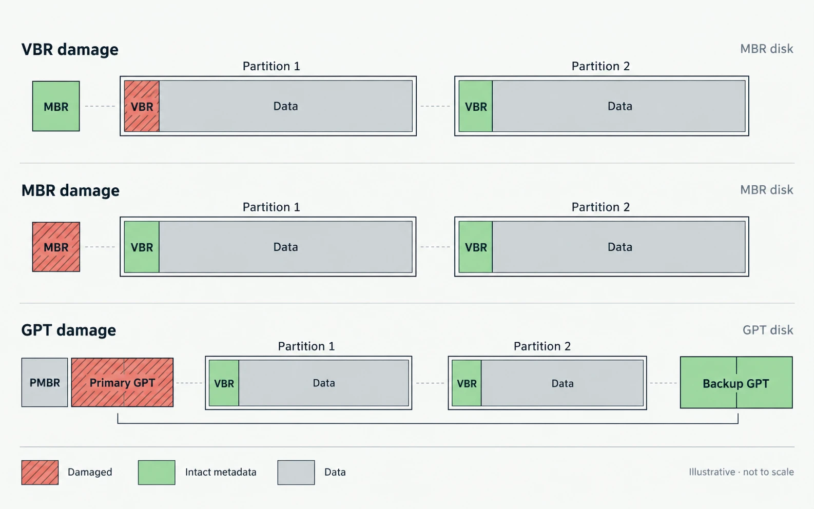
VBR Damage vs. MBR or GPT Damage
These failures affect different storage layers.
- MBR damage: May affect legacy bootstrap code or the partition entries stored at disk LBA 0.
- GPT damage: May affect the partition layout, GPT headers, or partition entry arrays.
- VBR damage: Affects the initial boot-related structure of a specific volume.
- EFI System Partition damage: May prevent UEFI firmware from locating or loading the Windows EFI boot manager.
The repair procedure must match the damaged component.
예를 들어, 부트레크 /fixmbr rewrites MBR boot code; it does not reconstruct a damaged NTFS VBR, repair GPT headers, or restore missing partition entries.
For a related explanation of disk-level boot problems, see Amagicsoft’s MBR corruption guide.
If important files are inaccessible, protect the original data before attempting a write-based repair. Avoid formatting, initializing, repartitioning, or running repair commands that modify the file system before securing a suitable backup or image.
결론
A Volume Boot Record is a volume-level structure that connects file-system parameters with boot-related information. Its position is normally the first logical sector of a volume, while its exact layout depends on the file system.
The distinction between MBR, GPT, and VBR is essential: MBR and GPT describe disk-level partition layouts, whereas the VBR belongs to a file-system volume. Legacy BIOS startup may execute VBR bootstrap code, while native UEFI startup loads an EFI application from the EFI System Partition.
Understanding the differences between NTFS, FAT32, and exFAT boot structures also helps distinguish a damaged boot record from broader file-system corruption or actual user-data loss.
자주 묻는 질문
Is a Volume Boot Record the Same as a Partition Boot Record?
Is the VBR Always Located at LBA 0?
Does a GPT Disk Have a Volume Boot Record?
Does UEFI Use the Volume Boot Record?
What Does the 55 AA Signature Mean in a Boot Sector?
55 AA are a boot signature used by several traditional boot-sector formats. Their presence is a useful structural indicator, but it does not prove that the BPB, file-system parameters, bootstrap code, or backup structures are valid.Where Is the Backup VBR Located?
BPB_BkBootSec, often sector 6. NTFS layouts commonly place a backup boot sector at the final volume sector in later Windows NT versions. exFAT uses a separate Backup Boot Region starting at volume-relative sector 12.Can a Damaged VBR Cause Permanent Data Loss?

바실리는 이 분야에서 약 10년간 실무 경험을 쌓은 데이터 복구 전문가입니다. 그는 경력 전반에 걸쳐 삭제된 파일, 포맷된 드라이브, 손실된 파티션 및 RAW 파일 시스템과 관련된 수천 건의 복잡한 사례를 성공적으로 해결했습니다. 그의 전문 지식은 헥스 에디터와 같은 전문 도구를 사용한 수동 복구 방법과 복구 소프트웨어를 사용한 고급 자동화 솔루션을 모두 다룹니다. 바실리의 사명은 IT 전문가와 일반 사용자 모두에게 신뢰할 수 있는 데이터 복구 지식을 제공하여 소중한 디지털 자산을 보호할 수 있도록 돕는 것입니다.