
Fragmented File Recovery Test: Carving Results
A fragmented file recovery test should first establish where each part of a file is stored. On NTFS, the nonresident $DATA attribute can describe that layout through Data Runs. We compare a contiguous PNG with the same PNG spread across three extents, then show why reading the fragmented layout as consecutive clusters fails. Finally, we follow the retained cluster mapping and verify the reconstructed bytes using SHA-256 and PNG CRC checks.
Table of Contents
Research Question: What Changes When a File Is Fragmented?
A file may be logically continuous even when its storage allocation is not. The application requests bytes in file order, while the file system translates those requests into locations on the volume. However, a raw content scanner may have to infer the locations without the benefit of that translation. This distinction becomes important when the file’s signature remains recognizable but later clusters are no longer adjacent.
In this fragmented file recovery test, we change two conditions: the locations of the second and third data clusters and the reader’s knowledge of their order. By contrast, file deletion, NTFS record damage, and overwriting create additional problems because they affect whether clusters or their mapping remain available.
Fragmented File Recovery Test Setup and File Layout
The fragmented file recovery test uses a 60 × 60-pixel RGB PNG containing 10,928 bytes. Its contents stay identical across all three scenarios. Because each cluster holds 4,096 bytes, the PNG spans three clusters. Consequently, the third cluster contains 1,360 bytes of allocation space beyond the logical end of the file. Cluster numbers below use a volume-relative LCN address scheme; they are not physical sector addresses.
The layout uses NTFS-style virtual cluster numbers (VCNs) for file order and logical cluster numbers (LCNs) for locations on the volume. For the contiguous layout, VCNs 0, 1, and 2 map to LCNs 40, 41, and 42. By contrast, the fragmented layout maps them to LCNs 40, 73, and 106. Meanwhile, the other positions hold unrelated bytes. Throughout the fragmented file recovery test, the PNG content stays fixed. Only cluster placement and the reader’s available mapping change.
Data Run Comparison: One Extent vs Three
Inspect the mapping pairs in the nonresident $DATA attribute before looking at extracted file bytes. The first byte of each run identifies field sizes, the next value gives the run length in clusters, and the signed LCN delta locates its starting cluster. In this test, the contiguous layout has one Data Run; the fragmented layout has three. The last 00 terminates the runlist. These mapping-pair bytes are encoded from the experiment allocation; they were not extracted from a physical MFT record.
S1 · Contiguous allocation
Single extent — no gaps between file clusters
11: 1-byte run length + 1-byte signed LCN delta; 00: end of runlist.| Run | Bytes | VCN | LCN | Length |
|---|---|---|---|---|
| 1 | 11 03 28 | VCN 0–2 | LCN 40–42 | 3 |
| File offset | VCN | Actual LCN | Read LCN |
|---|---|---|---|
0x0000 | VCN 0 | 40 | 40 ✓ |
0x1000 | VCN 1 | 41 | 41 ✓ |
0x2000 | VCN 2 | 42 | 42 ✓ |
All three requested clusters follow the on-volume sequence. A sequential reader reproduces the file.
S2 · Fragmented allocation / wrong sequential read
Three extents — actual second and third clusters are elsewhere
11: 1-byte run length + 1-byte signed LCN delta; 00: end of runlist.| Run | Bytes | VCN | LCN | Length |
|---|---|---|---|---|
| 1 | 11 01 28 | VCN 0 | LCN 40 | 1 |
| 2 | 11 01 21 | VCN 1 | LCN 73 | 1 |
| 3 | 11 01 21 | VCN 2 | LCN 106 | 1 |
| File offset | VCN | Actual LCN | Read LCN |
|---|---|---|---|
0x0000 | VCN 0 | 40 | 40 ✓ |
0x1000 | VCN 1 | 73 | 41 ✕ |
0x2000 | VCN 2 | 106 | 42 ✕ |
A basic contiguous reader skips the actual VCN 1 and VCN 2 locations. The first wrong file byte occurs at 0x1000.
The encoding makes the difference explicit. In S1, 03 means three clusters and 28 sets the starting LCN to 40. In S2, each run has length 01. Its signed LCN deltas are 28 (+40), 21 (+33), and 21 (+33), producing LCN starts 40, 73, and 106. Unlike file-offset Hex, these bytes describe the file’s allocation layout. For the NTFS encoding rule, see NTFS Data Runs documentation.
The test uses three scenarios:
- Scenario1 — Contiguous baseline: Read the PNG sequentially from LCN
40through42. - Scenario2 — Fragmented, mapping unavailable to the reader: Keep the file at LCNs
40,73, and106, but continue reading consecutive clusters beginning at LCN40. - Scenario3 — Fragmented, mapping available: Read the fragmented clusters in the correct VCN order, then trim the result to the original logical file length.
Method: We placed the PNG bytes in a cluster-addressed test array and extracted them using the three read paths. We then checked each stream through full-byte comparison, SHA-256, and PNG chunk CRCs. We supplied the cluster map instead of extracting it from an NTFS MFT record. Therefore, these checks establish byte reconstruction outcomes, not physical-drive or recovery-software performance.
Experiment Procedure
This fragmented file recovery test uses the same original bytes in every scenario. The five steps below isolate layout and mapping from file-content changes.
- Establish the source. Create the PNG, record its length and SHA-256 digest, and verify its signature, chunk structure, and chunk CRC values.
- Build S1. Place successive 4,096-byte portions of the file into LCNs
40,41, and42. Read forward from the PNG signature and validate the reconstructed stream. - Build S2. Place the same portions at LCNs
40,73, and106. Leave the intervening positions filled with unrelated bytes. Apply the same forward, consecutive-cluster read beginning at LCN40, without supplying the reader a cluster map. - Build S3. Keep the fragmented storage layout unchanged, but supply the ordered VCN-to-LCN mapping. Next, reassemble the three portions and remove padding beyond the original file length.
- Compare outcomes. First, inspect the cluster boundaries at file-relative offsets
0x1000and0x2000. Then validate PNG chunk CRCs and compare the full reconstructed stream with the source digest.
For direct comparison, S2 reads exactly 10,928 bytes, matching the source file length. A signature-based carver would not automatically know that length; it would need to determine the file boundary from PNG structure, available metadata, or other evidence. Even so, the consecutive read already fails PNG validation, independently of how the reader determines file length.
Fragmented File Recovery Test Results
S1: Contiguous File Recovery Success
S1 starts with the nonresident $DATA runlist 11 03 28 00. It describes one extent containing three clusters starting at LCN 40. Therefore VCN 0, 1, and 2 resolve to LCN 40, 41, and 42. The simple consecutive reader follows exactly those locations, so its 10,928-byte output matches the source SHA-256 and passes PNG chunk CRC checks.
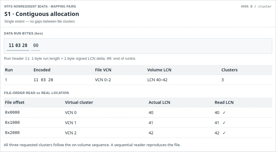
Figure 1. Contiguous file: a single Data Run maps VCN 0–2 to LCN 40–42.
A correctly identified file signature is useful here because the following data happens to remain sequential. In other words, sequential allocation explains this instance of contiguous file recovery success. A signature by itself does not establish complete recovery; the content must still satisfy the relevant format and integrity checks.
S2: File Carving Fragmented Files Experiment
In S2, the file contents do not change, but the nonresident $DATA runlist becomes 11 01 28 11 01 21 11 01 21 00. Decoding it reveals three separate one-cluster extents: VCN 0 → LCN 40, VCN 1 → LCN 73, and VCN 2 → LCN 106. A basic signature-based reader that ignores those extents instead assumes the next clusters are LCN 41 and 42. That incorrect assumption, not fragmentation itself, causes the candidate file to contain unrelated bytes from file offset 0x1000.
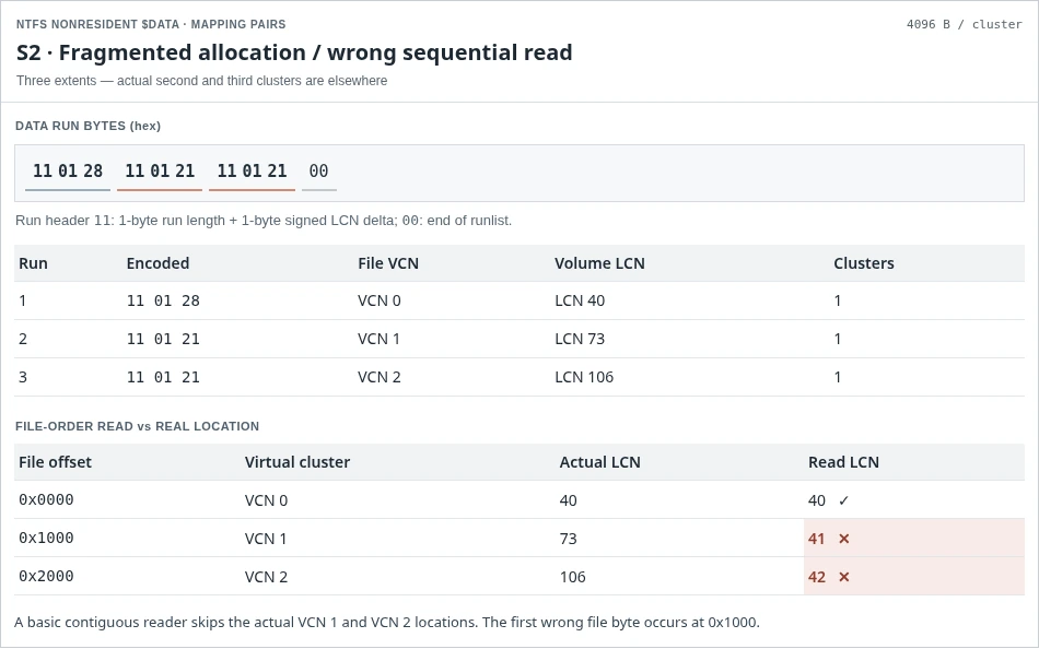
Figure 2. Fragmented file: three Data Runs map VCN 0, 1, and 2 to LCN 40, 73, and 106.
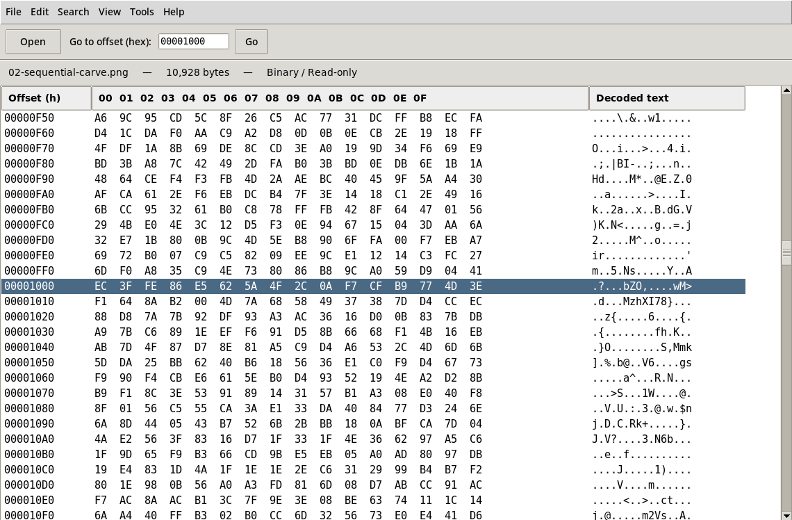
Figure 3. S2 Hex evidence at file offset 0x1000: the sequential read enters unrelated LCN 41 instead of LCN 73.
The Hex comparison therefore shows identical bytes before 0x1000 and a clear mismatch at the boundary. Thus, S2 has a correct 4,096-byte prefix followed by unrelated data. As a result, the PNG parser reports an IDAT CRC mismatch. In addition, the candidate stream has a different SHA-256 digest from the source. The incorrect data placement—not a change in the original image—is enough to explain the failure.
S3: Reconstructing a Fragmented File With Its Cluster Map
S3 uses the same fragmented runlist and the same cluster contents as S2. It does not defragment the file or rewrite a Data Run. Instead, the reconstruction reads LCN 40 → 73 → 106 in VCN order and trims the allocation padding to the original 10,928-byte file length. The resulting output matches the source SHA-256, and its PNG chunk CRCs pass. This is metadata-guided reconstruction, not signature-only file carving.
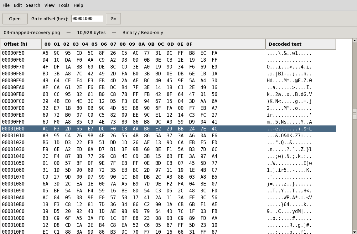
Figure 4. S3 reconstructed Hex at 0x1000: correct VCN-to-LCN reading restores the original bytes. Compare with Figure 3.
The reconstructed stream matches the source at both inspected cluster boundaries. Its SHA-256 matches the original digest, and all PNG chunk CRCs pass. These checks establish exact byte reconstruction when the correct mapping and every required cluster are available. However, an actual recovery case must first establish whether deletion, formatting, or file-system damage has destroyed the mapping or file bytes.
What the Byte Comparison Proves
The fragmented file recovery test produces exact 10,928-byte matches in S1 and S3, but not in S2. The first mismatch occurs at file offset 0x1000, exactly where the sequential read advances to the wrong cluster. The byte and CRC checks establish the central finding: a contiguous-read assumption works only when the file’s allocation follows that same sequence.
The Data Runs establish the allocation difference, while Figures 3 and 4 show the consequence at file offset 0x1000. Figure 3 shows unrelated data from LCN 41. Figure 4 shows the original bytes recovered by reading the actual second fragment at LCN 73. File-offset Hex is a secondary integrity check; the Data Runs are the evidence of fragmentation.
Why Fragmented File Recovery Results Differ
Microsoft’s explanation of clusters and extents distinguishes file-relative VCNs from volume-relative LCNs. Consequently, a single file can occupy several extents without placing them at adjacent volume locations. That is why a file whose logical bytes are ordered can nevertheless be scattered across a volume.
For example, on NTFS the nonresident attribute record structure can store the VCN-to-LCN mapping. Readers looking for the underlying file-record mechanism can consult the NTFS Master File Table guide. For a fuller explanation of how surviving mappings affect recovery, see File System Metadata Recovery. Those resources explain how the file system maintains the mapping; this test demonstrates what happens when that order is preserved, ignored, or restored.
The W3C PNG specification provides a separate way to examine content. For example, a PNG starts with an eight-byte signature and contains structured chunks, including IHDR, IDAT, and IEND. In addition, every PNG chunk stores a CRC for its chunk type and data. Accordingly, a recognizable PNG header does not mean all subsequent image data are valid. In S2, the parser reaches incorrect bytes while checking IDAT, making the corruption detectable.
However, file carving fragmented files is not limited to one naive forward-read strategy. Advanced carvers can examine chunk lengths, CRC constraints, compression properties, and candidate fragment relationships to infer missing boundaries. For example, a DFRWS study of syntactical PNG carving explores approaches that may recover fragmented PNG files without the original cluster map. The S2 result therefore describes the defined baseline method, not every existing or future carver.
Fragmented File Recovery: Practical Interpretation and Limits
The main lesson from this fragmented file recovery test is the difference between surviving file bytes and surviving knowledge of their order. All three PNG portions are present in S2, yet simple sequential reading cannot assemble them. In S3, the same portions form a valid file once the correct mapping guides the read. Therefore, neither a recognizable header nor a plausible filename proves that a recovered file contains all required content.
In a damaged or deleted-file case, the original mapping might no longer exist. For instance, later writes may overwrite an NTFS nonresident mapping or reuse its owning record. Likewise, a deleted FAT32 file may no longer retain its original FAT chain. An exFAT file can use contiguous allocation or a FAT chain, depending on its stream flags. For the relationship between metadata, allocation, and lost file links, see Orphaned Files and Lost Cluster Chains.
Moreover, reassembly is different from restoring bytes that no longer exist. Even with a correct mapping, recovery cannot reconstruct overwritten bytes. Similarly, a mapping cannot recreate old SSD content that the device no longer exposes after a discard operation. Although fragment-aware carving may help when the map is missing, it cannot guarantee correct ordering for every file format or storage condition.
For an actual recovery investigation, prevent further writes to the source and analyze a verified copy whenever possible. Then check allocation evidence and reconstructed content separately. Even so, a file that opens in an application may still be incomplete. A checksum match against a trusted original provides stronger evidence of exact reconstruction. By contrast, a digest calculated only after recovery identifies the output but cannot independently prove correctness.
Conclusion
This fragmented file recovery test shows why storage order matters, even when every fragment remains available. The contiguous read in S1 reproduces the original PNG, and the mapped fragmented read in S3 does the same. In S2, consecutive reading fails as soon as it crosses into an unrelated cluster. The first differing offset, failed PNG CRC, and SHA-256 comparisons make the distinction clear.
The Data Runs explain the allocation difference directly: S1 encodes one three-cluster extent, while S2 and S3 encode the same three one-cluster extents. What changes between S2 and S3 is whether the reader uses that mapping.
However, the broader lesson is not that fragmentation makes recovery impossible. It is that file carving, cluster mapping, and file-format validation answer different questions. Therefore, a reader must identify the correct fragments, place them in order, and verify the reconstructed content before claiming complete recovery. Ultimately, success on a real device depends on what evidence survives.
Fragmented File Recovery Test FAQs
Why is contiguous file carving usually easier?
Does file carving always fail on fragmented files?
How can NTFS metadata help recover a fragmented file?
$DATA attribute can provide VCN-to-LCN mapping information that identifies the file's extents. For a fragmented file recovery test, that mapping explains which clusters the reader must join. If the mapping is still valid and the referenced clusters remain readable, a recovery process can concatenate those clusters in their original order. An old mapping cannot restore overwritten content.Can a correct file header prove that recovery succeeded?
Is knowing the original file size enough to rebuild fragments?
Does a matching SHA-256 guarantee recovery of an unknown file?
What does the CRC mismatch tell us about the recovered file?
0x1000. The IDAT chunk CRC no longer matches its stored value. That mismatch identifies corrupted chunk contents, although a valid CRC by itself would not prove that every aspect of a recovered image is correct.
Vasilii is a data recovery specialist with around 10 years of hands-on experience in the field. Throughout his career, he has successfully solved thousands of complex cases involving deleted files, formatted drives, lost partitions, and RAW file systems. His expertise covers both manual recovery methods using professional tools like hex editors and advanced automated solutions with recovery software. Vasilii's mission is to make reliable data recovery knowledge accessible to both IT professionals and everyday users, helping them safeguard their valuable digital assets.